Scenic Draft: A No Dependency WebGL2 Raymarching SDF CSG Renderer Library
I was impressed by Piter Pasma's Skulptuur, which uses raymarching to create 3D sculptures. I wanted to try turning that approach into a small library for building and rendering my own scenes.
scenic-draft lets you describe a 3D scene in TypeScript. It compiles the shapes and background into a GLSL shader, then renders them on a WebGL2 canvas. The image starts noisy and becomes clearer as samples accumulate.
Install it with pnpm add scenic-draft. The core library has no dependencies. It generates a shader from the scene data, then runs it with a small WebGL2 path tracer.
The shapes use signed distance functions (SDFs), which make them easy to combine, blend and hollow out. Let's build up from one sphere to a complete scene. The images below were rendered ahead of time with the library and saved as files.
Raymarching and signed distance functions
A signed distance function answers one question about a point in space: how far away is the nearest surface? The value is zero exactly on the surface, positive outside, negative inside. A sphere of radius r centred at the origin is just:
float sphere(vec3 p) {
  return length(p) - r;
}
To find a surface, we send a ray from the camera through each pixel. The SDF tells us how far we can move along it without crossing any geometry. We evaluate the distance, move by that amount and repeat.
This is called sphere tracing: each safe step is the radius of a sphere around the current point. We stop when the distance is very small, or when the ray passes the far limit and reaches the background.
Let's start with one sphere. The default material is polished gold:
import { gradient, render, sphere } from 'scenic-draft'

render(canvas, {
  background: gradient([0.02, 0.03, 0.05], [0.85, 0.9, 1.0]),
  scene: sphere(1.5),
})
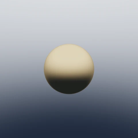
sphere(1.5) compiles directly to length(p) - 1.5 in the shader's map() function. No triangle mesh is created.
The same scene data produces the same shader. Changing the scene means compiling a new shader and starting the render again. The examples below build more complex distance functions by combining simple ones.
The background is the light
The sphere is lit by its background. Rays bounce through the scene and sample the environment when they escape. This provides the lighting and reflections in this example.
With the same colour arriving from every direction, there is little contrast to reveal the shape:
import { solid, sphere } from 'scenic-draft'

render(canvas, {
  background: solid([0.55, 0.6, 0.7]),
  scene: sphere(1.5),
})
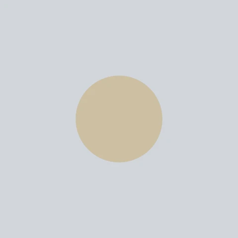
The gold sphere now looks almost like a disc. If a scene looks flat, try changing the background. A gradient gives different light from above and below, and a sun adds a directional light and shadows.
Primitives
Primitives start at the origin; transforms place them in the scene. The builders reject invalid arguments, such as a negative radius.
| Builder | Shape |
|---|---|
sphere(radius) | A sphere. |
box(halfExtents, rounding?) | A box given as half-extents, so box([1, 0.5, 1]) is 2 wide, 1 tall, 2 deep. rounding inflates the edges. |
torus(major, minor) | A ring around the y axis: major ring radius, minor tube radius. |
cylinder(radius, halfHeight) | A capped cylinder along y. |
capsule(radius, halfHeight) | A capsule along y; halfHeight is the straight section. |
plane(normal, offset?) | A half-space, solid below the plane. plane([0, 1, 0], -1) is a floor at y = −1. |
Here they all are, painted matte and lined up on a floor plane. Note the placement arithmetic: with the floor at y = −1, a sphere of radius 0.7 sits at y = −0.3, and a torus with tube radius 0.25 rests at y = −0.75.
union(
  paint(plane([0, 1, 0], -1), { color: [0.5, 0.5, 0.53], roughness: 0.9 }),
  paint(translate(sphere(0.7), [-3, -0.3, 0]), { color: [0.85, 0.25, 0.2] }),
  paint(translate(box([0.6, 0.6, 0.6], 0.03), [-1.5, -0.4, 0]), {
    color: [0.9, 0.6, 0.2],
  }),
  paint(translate(cylinder(0.5, 0.7), [0, -0.3, 0]), {
    color: [0.2, 0.6, 0.35],
  }),
  paint(translate(capsule(0.45, 0.5), [1.5, -0.05, 0]), {
    color: [0.25, 0.5, 0.85],
  }),
  paint(translate(torus(0.6, 0.25), [3, -0.75, 0]), {
    color: [0.6, 0.3, 0.75],
  }),
)
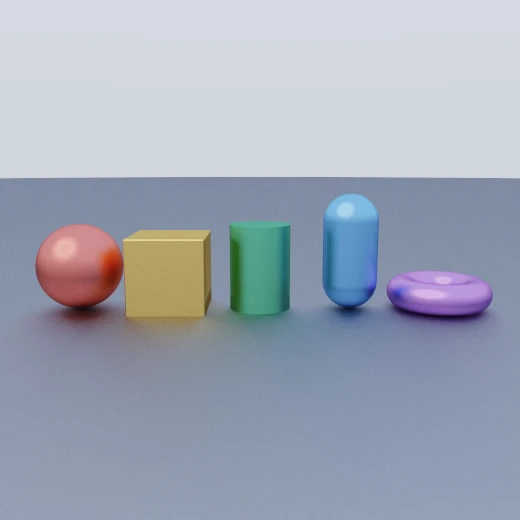
plane represents a solid half-space, not a thin sheet. We can use it as a floor or to cut another shape along a flat surface.
Placing things: transforms
Transforms wrap a shape or group of shapes. We can nest them to position an object:
translate(node, [x, y, z])to move it.rotateX(node, radians),rotateYandrotateZto rotate about a world axis.scale(node, factor)for a uniform scale.
The shader applies the inverse transform to the query point. For example, rotating the point backwards lets us measure the distance to a rotated shape. This takes a few arithmetic operations per step.
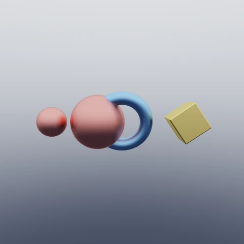
Here two spheres share a builder but differ by scale, a torus is tilted with rotateX, and a rounded box is spun with rotateZ, all spread out with translate:
union(
  translate(scale(sphere(1), 0.55), [-2.6, 0, 0]), // scaled down
  translate(sphere(1), [-0.9, 0, 0]), // full size
  rotateX(torus(0.9, 0.24), Math.PI / 2.3), // tilted ring
  translate(rotateZ(box([0.5, 0.5, 0.5], 0.04), 0.6), [2.4, 0, 0]),
)
Constructive solid geometry
Constructive solid geometry combines simple shapes using boolean operations. With distance fields, these operations use min and max:
Union
union(...nodes) combines the shapes. It takes the minimum of their distances. Here two spheres join into one solid, with a sharp crease where they meet:
union(
  paint(sphere(1), { color: [0.2, 0.45, 0.85] }),
  paint(translate(sphere(0.8), [1.1, 0.55, 0]), { color: [0.9, 0.5, 0.2] }),
)
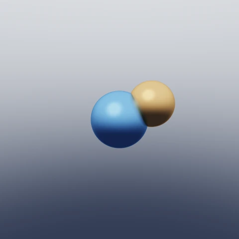
Notice each sphere keeps its own colour. On a surface produced by a boolean, the material is picked from the nearest contributing primitive, so the seam is exactly where blue gives way to orange.
Intersection
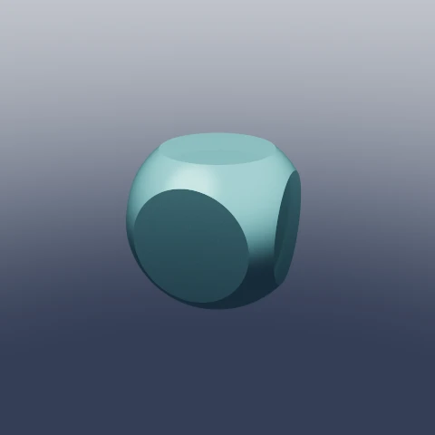
intersect(...nodes) keeps only the overlap, using max() on the distances. Here a sphere clips the corners of a box:
intersect(box([1, 1, 1], 0.05), sphere(1.32))
Subtraction
subtract(base, ...cuts) removes shapes from the base, using max(base, -cut). Let's take the clipped cube and cut a cylindrical hole along each axis.
Because scene nodes are plain data, one bore cylinder can be reused three times, rotated onto each axis:
const bore = cylinder(0.6, 1.6)

subtract(
  intersect(box([1, 1, 1], 0.05), sphere(1.32)), // rounded cube ∩ sphere
  bore, // hole along y
  rotateX(bore, Math.PI / 2), // hole along z
  rotateZ(bore, Math.PI / 2), // hole along x
)
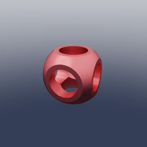
Four primitives and three boolean operations describe the result. The scene is a JavaScript value, so we can generate it with code, save it as JSON or compare it in a test.
Smooth booleans
Smooth booleans blend the join between shapes. They use Inigo Quilez's polynomial smooth minimum, with k controlling the width of the blend:
smoothUnion(k, ...nodes)melts shapes together like wax.smoothIntersect(k, ...nodes)gives a blended overlap.smoothSubtract(k, base, ...cuts)gives a rounded groove instead of a sharp lip.
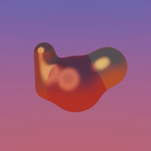
Try k: 0.1 for a small rounded join, or 0.5–1 for a softer, more organic shape. Here three shapes blend with k: 0.5:
smoothUnion(
  0.5,
  paint(sphere(1), { color: [0.9, 0.35, 0.2] }),
  paint(translate(sphere(0.7), [1.1, 0.6, 0]), { color: [0.95, 0.7, 0.25] }),
  paint(translate(capsule(0.35, 0.6), [-1.05, 0.5, -0.15]), {
    color: [0.9, 0.5, 0.2],
  }),
)
The same idea works in reverse. smoothSubtract scoops material away but leaves the rim rounded rather than sharp. Here a sphere is smoothly subtracted from the top of a slab to make a soft dish:
smoothSubtract(
  0.3,
  box([1.3, 0.75, 1.3], 0.06),
  translate(sphere(0.95), [0, 0.85, 0]),
)
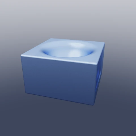
Changing smoothSubtract to subtract gives the dish a sharp rim. This is a useful way to adjust the character of an edge with a small code change.
Modifiers: shells and rounding
Two more operators work on whatever is inside them, boolean results included.
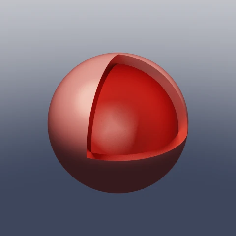
shell(node, thickness) hollows out a solid using abs(d) - thickness. To see inside, we'll subtract a box that removes one octant:
subtract(
  shell(sphere(1.25), 0.08), // a sphere with 8cm-ish walls
  translate(box([1, 1, 1]), [1, 1, -1]), // remove one octant to expose the inside
)
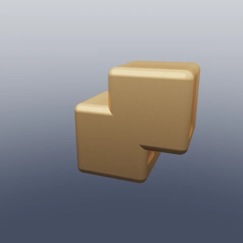
grow(node, amount) expands a surface, rounding its edges. A negative amount shrinks it. It also works on boolean results, such as this union of two boxes:
grow(
  union(box([0.7, 0.7, 0.7]), translate(box([0.7, 0.7, 0.7]), [0.85, 0.85, 0])),
  0.18,
)
Materials
So far most shapes have carried a colour. Materials are applied with paint(node, material), which covers every primitive in the subtree. A material is small:
interface Material {
  color: Vec3 // base colour, linear-ish RGB 0..1
  roughness?: number // 0 = mirror, 1 = fully rough   (default 0.4)
  metallic?: number // 0 = dielectric, 1 = metal     (default 0)
}
metallic gives us two broad kinds of surface:
- Dielectrics (
metallic: 0) are plastic, ceramic and stone. The colour is the diffuse colour, and reflections are white and strongest at grazing angles (a Fresnel effect the tracer models directly). - Metals (
metallic: 1) take on the material's own colour in their reflections, which dominate at every angle.roughnessdecides whether that reflection is a sharp mirror or a soft sheen.
Nested paint calls let us colour a group, then override individual parts. Here are a blue plastic sphere, a gold sphere and a red object with a chrome ring. The ring's own material overrides the enclosing red one:
union(
  paint(plane([0, 1, 0], -1), { color: [0.55, 0.55, 0.58], roughness: 0.9 }),
  paint(translate(sphere(0.8), [-2, -0.2, 0.3]), {
    color: [0.15, 0.4, 0.85],
    roughness: 0.25,
    metallic: 0, // plastic
  }),
  paint(translate(sphere(0.8), [0, -0.2, 0.3]), {
    color: [0.95, 0.75, 0.4],
    roughness: 0.15,
    metallic: 1, // metal
  }),
  translate(
    paint(
      union(
        box([0.55, 0.55, 0.55], 0.06),
        paint(rotateX(torus(0.85, 0.13), Math.PI / 2), {
          color: [0.9, 0.9, 0.92],
          roughness: 0.06,
          metallic: 1, // chrome ring wins
        }),
      ),
      { color: [0.75, 0.12, 0.1], roughness: 0.5 }, // everything else: matte red
    ),
    [2, -0.35, 0.3],
  ),
)
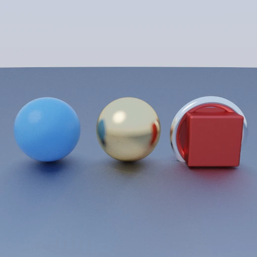
The same nearest-primitive rule from the boolean section applies here. Subtract a red sphere from a blue box and you get a red-lined crater, because the carved surface belongs to the sphere.
Backgrounds, suns and the camera
Because the background is the light, it deserves more than a flat colour. Three builders cover it:
solid(color)                      // one colour everywhere — flat light
gradient(bottom, top, options?)   // vertical sky/ground blend
sun(direction, color, sharpness?) // a directional glow, for gradient()
gradient(bottom, top, { horizon, width, sun }) blends from the colour rays see looking down to the colour they see looking up. horizon shifts where the blend sits and width sets how soft it is, so a small width gives a hard horizon line.
sun(direction, color, sharpness) adds a bright disc to the background. Colour components above 1 make it brighter; sharpness controls its size. A smaller, sharper disc gives harder shadows.
For example, sun([-0.5, 0.8, -0.3], [7, 6, 4.5], 80) gives a bright, warm light. The sunset example uses a lower sun over a dim sky.
The camera is an optional pinhole:
interface CameraSpec {
  position: Vec3 // default [0, 1.5, -8]
  target?: Vec3 // default [0, 0, 0]
  focalLength?: number // the lens, in millimetres. default 35
  sensor?: number // what it projects onto, in millimetres. default 36
}
The camera looks from position towards target, with +y up. focalLength and sensor set the field of view; a longer focal length gives a narrower view.
These settings replaced zoom in 0.20.0, which also added fStop for depth of field. The compiler calculates the camera constants before rendering.
Putting it together
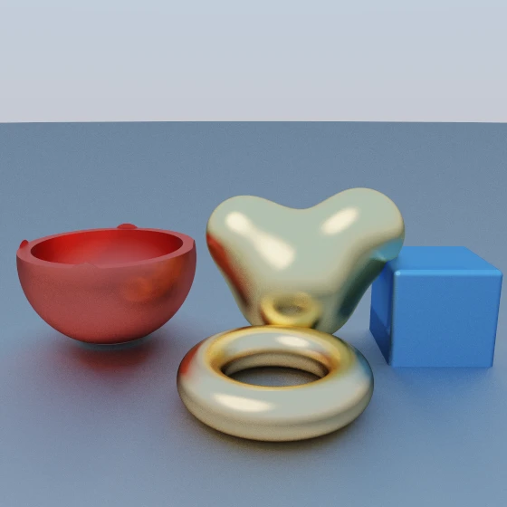
Now let's combine the examples: a floor, a hollow bowl, a blended metal shape, a die and a gold torus. A warm sun and gradient sky light the scene:
{
  background: gradient([0.5, 0.42, 0.36], [0.35, 0.55, 0.85], {
    sun: sun([-0.45, 0.7, -0.35], [7, 6, 4.5], 80),
  }),
  camera: { position: [0, 1.7, -6.4], target: [0, 0.05, 0], focalLength: 41 },
  scene: union(
    paint(plane([0, 1, 0], -1), { color: [0.62, 0.6, 0.58], roughness: 0.9 }),
    paint(
      translate(
        subtract(shell(sphere(0.95), 0.07), translate(box([1, 1, 1]), [0, 1.15, 0])),
        [-1.7, -0.05, 0.2],
      ),
      { color: [0.85, 0.2, 0.15], roughness: 0.3 },
    ),
    paint(
      translate(
        smoothUnion(0.4, sphere(0.75),
          translate(sphere(0.5), [0.7, 0.55, 0]),
          translate(sphere(0.45), [-0.6, 0.5, 0.1])),
        [0.5, -0.25, 0],
      ),
      { color: [0.9, 0.72, 0.35], roughness: 0.2, metallic: 1 },
    ),
    paint(translate(box([0.5, 0.5, 0.5], 0.06), [2, -0.5, -0.2]), {
      color: [0.2, 0.45, 0.85], roughness: 0.5,
    }),
    translate(torus(0.7, 0.22), [0.2, -0.78, -1.4]),
  ),
}
Rendering, and wiring it into React
render(canvas, spec, options?) sizes the canvas, compiles the shader and starts the render loop. Each frame adds one sample per pixel, and the running average becomes the displayed image. Call the returned handle's stop() during cleanup:
const handle = render(canvas, spec, { size: 512 })
// later, when the canvas goes away:
handle.stop()
In React that maps cleanly onto an effect:
export function SDExample({ size, scene }: { size: number; scene: SceneSpec }) {
  const canvasRef = useRef<HTMLCanvasElement>(null)

  useEffect(() => {
    const canvas = canvasRef.current
    if (!canvas) return
    const handle = render(canvas, scene, { size })
    return () => handle.stop()
  }, [scene, size])

  return <canvas ref={canvasRef} className="aspect-square w-full max-w-md" />
}
Keep spec stable, either outside the component or with useMemo. A fresh object restarts rendering. Always return the cleanup function; this also handles React's development-mode effect checks.
Optimising for multiple examples
Each canvas uses a WebGL2 context, and browsers limit how many can exist at once. For a page with many examples, use IntersectionObserver to mount canvases near the viewport and release their contexts when they leave.
Returning to a scene then starts rendering again. This page used to use that approach; it now shows saved images, which avoids doing the rendering on each reader's device.
The main cost controls are size, bounces and maxFrames. Doubling both image dimensions gives four times as many pixels. More bounces and frames improve some scenes, but take longer.
Metallic scenes often benefit from six or more bounces; simple matte scenes can look fine with four. The renderer requires WebGL2 and EXT_color_buffer_float, and reports an error if either is missing.
You can also inspect the generated shader without a GPU. buildShader(spec) returns it as a deterministic string, which is useful for debugging and tests:
import { buildShader, gradient, sphere } from 'scenic-draft'

const source = buildShader({
  scene: sphere(1.5),
  background: gradient([0, 0, 0.1], [1, 1, 1]),
})

source.includes('length(p) - 1.5') // true — the radius is baked into map()
Summary
That is enough to build a scene: describe the shapes, combine them with boolean operations, then add materials, lighting and a camera. The library turns that data into the shader for us.